< img height="1" width="1" style="display:none" src="https://www.facebook.com/tr?id=726265909755455&ev=PageView&noscript=1" />

Shanghai Metallurgy Group_Turnkey Steel Solution Supplier

News&Media
News&Media
/ Home / News&Media / News
Blast Furnace Clay Gun: A Critical Equipment Safeguarding Stable Molten Iron Tapping
2025-12-31

Blast Furnace Clay Gun: A Critical Equipment Safeguarding Stable Molten Iron Tapping

In the grand landscape of modern iron and steel smelting, the blast furnace serves as the core heart, while the blast-furnace gun ranks among the critical equipment that safeguards the stable operation of this "heart". Hailed as the "Patron Saint" of the tapping area in the smelting industry, its core mission is to rapidly, accurately and safely seal the iron taphole gushing with molten iron after the blast furnace tapping operation, thereby providing a solid guarantee for the continuous, stable and safe production of the blast furnace. The blast-furnace clay gun is not merely a simple mechanical device, but also an important supporting component for the high-pressure operation process of blast furnaces. 1.Core Process Functions The primary process task of the blast-furnace clay gun is to seal the iron taphole. During the blast furnace smelting process, molten iron and slag are periodically discharged from the taphole of the hearth. Upon completion of tapping, the taphole must be tightly sealed immediately with refractory material (namely "gun clay") to withstand the blast furnace gas pressure inside the furnace, which can reach several kilograms or even higher. This prevents gas leakage or molten iron splashing, ensuring that the blast furnace can continue the next smelting cycle in a sealed state. 2.Lining Repair and Maintenance This is a frequently overlooked yet crucial process function. During the clay-injecting operation of modern blast-furnace clay guns, the equipment not only fills the taphole channel that has been enlarged by the scouring of molten iron, but also extrudes a portion of the gun clay into the hearth interior. Under the combined effect of high pressure and high temperature inside the furnace, this part of the gun clay adheres to and solidifies on the inner wall of the hearth, forming a new protective layer (shaped like a mushroom). In this way, it repairs the damaged furnace lining and extends the service life of the blast furnace. 3.Adaptation to the Trends of High Pressure and Large Scale With the development of blast furnaces towards larger scale, higher pressure and longer service life, the internal pressure of the furnace is continuously increasing, which imposes extremely high requirements on the sealing tightness and the density of gun clay. This necessitates that the clay gun must be equipped with enormous clay-injecting thrust and stable compaction force, so as to ensure that the gun clay can overcome the high pressure inside the furnace to enter smoothly and adhere tightly to the furnace lining. From the equipment perspective, the blast-furnace clay gun is a sophisticated integrated system combining mechanics, hydraulics and electrical control. It has evolved from steam-driven and electric-driven models to the modern full-hydraulic-driven type. Currently, hydraulic clay guns have become standard equipment for modern large-scale blast furnaces, thanks to their advantages including high thrust, compact structure, smooth operation and easy implementation of remote automated control. 1.Equipment Structure and Components A complete hydraulic clay gun for blast furnaces is mainly composed of the following core mechanisms: Barrel (Clay Injection Mechanism): This is the "heart" of the clay gun. It consists of a clay cylinder and a clay pushing mechanism. The clay cylinder is used for storing and ejecting gun clay; it is usually made of high-strength chromium-molybdenum steel and undergoes glow ion nitriding treatment to enhance wear resistance and high-temperature resistance. The clay pushing mechanism (clay injection cylinder) provides powerful thrust to extrude gun clay out of the clay cylinder. Slewing Mechanism: This is the "arm" of the clay gun. It is composed of a slewing cylinder, a slewing arm, a base, etc. Its function is to smoothly move the barrel from the safe position on the side of the iron runner to the position directly in front of the iron taphole, and retract it after the taphole sealing is completed. Modern clay guns mostly adopt a low-profile design; in the non-operating state, the entire barrel is positioned below the tuyere platform without affecting the traffic and structural integrity of the platform. Pressing and Locking Mechanism: This is the "gripper" of the clay gun. After the gun nozzle is aligned with the iron taphole, this mechanism uses the enormous force generated by the hydraulic system to firmly press the nozzle against the clay sleeve of the taphole, withstanding the huge counter-thrust during clay injection and preventing clay leakage or equipment retraction. Hydraulic and Electric Control System: This is the "nervous system" of the clay gun. The hydraulic station supplies power and controls the action sequence, speed and pressure of the cylinders through complex valve groups. The electric control system realizes functions such as remote operation, status monitoring and safety interlocking, ensuring that operators can control the equipment in a safe room away from high-temperature hazardous areas. 2.Key Technical Requirements To meet stringent process requirements, the design of blast furnace clay guns must comply with the following standards: Sufficient Thrust and Pressure: The clay injection thrust generally needs to reach hundreds or even thousands of kilonewtons (kN), and the clay pressure at the nozzle outlet should reach (30–40)×10⁵ Pa, so as to overcome the frictional resistance of the taphole channel and the coke resistance inside the furnace. Precise Movement Trajectory: The movement trajectory of the gun nozzle must be extremely accurate to ensure one-time alignment with the iron taphole. Modern designs usually adopt a special linkage mechanism (e.g., four-bar linkage mechanism), which makes the movement trajectory of the nozzle approximately linear when approaching the taphole, so as to protect the taphole clay sleeve from collision damage. Reliable Sealing and Thermal Insulation: Given the extremely high-temperature working environment, the equipment must be equipped with a complete set of thermal insulation shields and cooling systems to prevent high-temperature radiation from damaging hydraulic components and seals. Evolution and Intelligent Development TrendsEarly steam-driven clay guns have been phased out due to insufficient thrust. Although electric-driven clay guns feature a simple structure, their thrust improvement is limited and they are prone to wear. The advent of hydraulic clay guns has addressed these drawbacks. Currently, with the advancement of Industry 4.0, intelligent clay gun robots are emerging. These robots integrate AI visual recognition technology, which enables automatic identification of taphole conditions and fully automated, unmanned taphole sealing operations, thereby further enhancing operational safety and efficiency. In summary, the blast-furnace clay gun is a key node that links the "dynamic" and "static" states, as well as the "opening" and "closing" operations of a blast furnace. It is not only a guardian of the blast furnace’s long campaign life and smooth operation, but also an epitome of technological progress in the iron and steel industry. From the cumbersome machinery in the early days to the sophisticated and intelligent equipment today, every technological iteration of the blast-furnace clay gun has been contributing to the high efficiency, safety and green development of iron and steel production.

Cooling Bed in Steel Rolling Production Lines: Structure, Types, and Process Functions | SMG Group
2025-12-16

Cooling Bed in Steel Rolling Production Lines: Structure, Types, and Process Functions | SMG Group

Cooling Bed in Steel Rolling Production Lines — Structure, Process Functions and Intelligent Development The cooling bed is an indispensable auxiliary equipment in the steel rolling production line, primarily used for the cooling and transportation of steel after hot rolling. Its design and operation are directly related to product quality, production efficiency, and subsequent processing performance. From the perspectives of equipment and process, the cooling bed plays multiple roles in modern steel rolling systems. 1.Equipment Structure and Types Essentially, a cooling bed is a mechanized platform integrating cooling and transmission functions. Common forms include walking-beam, circular roll, chain, inclined roll, and reciprocating pawl types. Among them, the walking-beam cooling bed is widely used in bar and section steel production lines due to its uniform cooling, neat arrangement of steel, and minimal scratching. The cooling bed consists of a transmission system, bed surface rollers or toothed plates, lifting devices, and alignment devices. Through periodic lifting and forward movements, the steel achieves full contact with the air during movement, realizing uniform cooling. Modern cooling beds also integrate automatic temperature measurement, alignment, and bundling functions. Combined with automated control systems, they achieve seamless connection from the hot rolling exit to finished product collection. Some high-end production lines adopt the "hot charging" process, directly sending high-temperature steel into slow cooling pits or heat treatment furnaces to avoid re-heating, thereby saving energy and reducing consumption. 2.Process Functions and Classifications According to cooling intensity and process requirements, cooling bed operations can be classified into three categories: natural cooling, forced cooling, and slow cooling. Natural Cooling (Air Cooling): This involves placing hot-rolled steel on the cooling bed surface to dissipate heat naturally in the atmosphere. It is suitable for ordinary carbon steel and low-alloy steel, featuring moderate cooling speed and low cost. It is the most widely used cooling method. It requires the final cooling temperature to be below 200°C to prevent straightening deformation or scratching. Forced Cooling: This accelerates heat dissipation through air cooling, mist spraying, or water cooling, used to refine grains, improve microstructure, and eliminate network carbides. For example, wire rod controlled cooling (Stelmor cooling) adopts an air cooling path to achieve a sorbite transformation, enhancing drawing performance. Slow Cooling: For stress-sensitive materials such as high-alloy steel and tool steel, pit cooling or furnace cooling methods are used to prevent the formation of flakes, cracks, or surface martensite. Although the cooling cycle is long, it is crucial for quality assurance. 3.Process Coordination and Intelligent Development The cooling bed is not an isolated device but an important link in the controlled rolling and controlled cooling (TMCP) process chain. Its cooling path, dwell time, arrangement density, and other parameters need to be dynamically matched with the rolling rhythm and steel specifications. Modern cooling beds are often linked with level-2 control systems. Combined with mathematical models to predict temperature drop, they achieve precise control of coiling temperature (±5°C), improving the uniformity of product microstructure and mechanical properties. Furthermore, the application of intelligent technologies such as queue storage technology and PID feedback control endows the cooling bed system with self-learning and self-adaptive capabilities, effectively dealing with disturbance factors such as ambient temperature and humidity and the initial temperature of the steel.

What Is an Edge Rolling Mill%3F Core Functions, Structure, and Benefits in Section Steel Production Lines
2025-12-3

What Is an Edge Rolling Mill%3F Core Functions, Structure, and Benefits in Section Steel Production Lines

Section Steel Edge Rolling Mill: Key Equipment for Precision Dimension Control in Modern Rolling Lines —Technology Insight by Shanghai Metallurgy Group (SMG Group) In modern section steel production, the edge rolling mill plays a decisive role in ensuring dimensional accuracy, stabilizing product quality, and supporting the continuous operation of the entire rolling line. As a core finishing-stage equipment, it connects roughing, intermediate rolling, and final straightening, acting as a critical bridge for precision shape control. 1. Why an Edge Rolling Mill Is Essential in Section Steel Production During the rolling process, section steel such as I-beams, channels, and angles may experience: Flange thickness deviation Cross-section asymmetry Edge burrs and scale Uneven rolling force distribution If these issues are not corrected before the finishing stage, the product will fail tolerance requirements, resulting in scrap and downtime. The edge rolling mill precisely applies controllable pressure to the flange or web edges, enabling: Flange thickness tolerance controlled within ±0.5 mm Removal of burrs and scale Correction of cross-section asymmetry Stabilized shape for straightening and cutting Through PLC communication, it automatically adjusts roll gaps and speeds based on incoming section data, ensuring seamless coordination and preventing losses during size changeovers 2. Structural Design Optimized for Precision Rolling The equipment adopts a double-frame symmetric structure, equipped with: Horizontal rolls for thickness calibration Side pressure rolls for width control and edge perpendicularity Roll material: Cr12MoV alloy steel, hardened to HRC 58–62 Withstands long-term rolling abrasion at 1200°C Drive System Features Variable-frequency motor + reducer Output torque up to 2000 N·m Stepless speed control from 0.5–3 m/s for different section profiles Intelligent Measurement Systems Infrared temperature detection Laser dimension measurement Automatic roll gap correction when deviations exceed preset tolerance This ensures consistent shape accuracy and reduces manual intervention. 3. Improved Energy Efficiency and Line Productivity Modern edge rolling mills adopt optimized systems that significantly reduce energy consumption: Hydraulic screw-down system 40% faster response than mechanical systems Roll gap precision up to 0.01 mm Integrated waste-heat recovery Recycles rolling heat for workshop heating Annual energy savings of approx. 15% In a large-scale section rolling plant, one edge rolling mill can support 500,000 t/year capacity. With stable operation, the product qualification rate can increase from 88% to over 98%, directly boosting the line’s economic efficiency.

What Is Water Quenching Cooling(TMT) in Hot Rolled Steel Production and How Does It Work%3F
2025-11-21

What Is Water Quenching Cooling(TMT) in Hot Rolled Steel Production and How Does It Work%3F

Water quenching cooling, also known as online rapid cooling, is a critical controlled cooling process in the production of hot-rolled steel. Its core principle is to immediately perform controlled rapid cooling on the steel after rolling and before it enters the cooling bed. The aim is to regulate the phase transformation process and microstructure of the steel, thereby obtaining specific mechanical properties and microstructures. This helps reduce or even eliminate subsequent heat treatment processes, ultimately achieving the goals of cost saving, efficiency improvement and product quality enhancement. I. From the Perspective of Process The process is the "soul" of water quenching cooling (online rapid cooling), as it defines the objectives, pathways, and parameters of the cooling process. 1. Core Process Objectives: Strength Improvement: Through rapid cooling, the transformation of austenite into coarse ferrite and pearlite is inhibited, while the formation of fine ferrite, bainite, and even martensite is promoted, thereby achieving grain refinement strengthening and phase transformation strengthening. For products such as rebars and wire rods, this enables them to reach high-strength grades (e.g., HRB500E, HRB600) without adding alloying elements (such as vanadium, niobium) or with reduced dosages of these elements. Toughness Enhancement: The refined grains not only improve strength but also significantly enhance the low-temperature impact toughness of steel. Control of Microstructure and Property Uniformity: Ensure consistent cooling rates across the cross-section and along the length of the steel, so as to obtain uniform mechanical properties and metallographic structure. Morphology Control: For wire rods, water quenching cooling can control the structure and thickness of the scale on their surface, reducing pickling time and acid consumption. 2. Key Process Parameters: Cooling Start Temperature: The surface temperature of the steel when it enters the cooling system. It must be higher than the phase transformation point (Ar3) to ensure the steel is in a fully austenitic state, enabling controlled phase transformation. Cooling End Temperature: The surface temperature of the steel when it exits the cooling system. As one of the most critical parameters, it directly determines the final phase transformation products and microstructure type. Cooling Rate: The magnitude of temperature drop per unit time. A faster cooling rate results in finer microstructure and higher strength. The cooling rate is controlled by water pressure, water volume, and cooling time. Cooling Time/Path: The duration the steel stays in the cooling zone. Together with the rolling speed, it determines the cooling length. By controlling the cooling path (e.g., "slow cooling - rapid cooling - self-tempering"), more complex microstructure regulation can be achieved. 3. Typical Process Route (Taking Rebar as an Example): Rolling → Temperature Measurement → Water Quenching Cooling → Temperature Measurement → Cooling Bed Entry Process Control Logic: Based on the rolling speed and final rolling temperature, the water pressure and flow rate of the water cooling system are calculated and adjusted in real time. This ensures that the final cooling temperature remains stable at the target set value, regardless of fluctuations in incoming material conditions. After the steel exits the water cooling system, the residual heat in the core is used to "self-temper" the martensite or bainite structure already formed on the surface, resulting in a tempered sorbite structure. This achieves a balance between high strength and excellent ductility-toughness. II. From the Perspective of Equipment Equipment is the "physical body" of the water quenching cooling process and serves as the physical guarantee for achieving process objectives. 1. Composition of Core Equipment: ① Water Tank/Cooler: Structure: Typically a closed box with densely arranged cooling water pipes or nozzle arrays inside. Sealing devices are installed at both ends of the water tank to prevent massive leakage of cooling water and ensure that the water flow tightly wraps around the steel. Nozzle Design: The most critical component. Annular slot nozzles or vortex nozzles are usually adopted, which can form a high-speed, uniform, and continuous water curtain. This water curtain breaks the vapor film on the steel surface (Leidenfrost effect), enabling efficient nucleate boiling heat transfer and ensuring extremely high cooling efficiency. ② High-Pressure Water Supply System: Composition: Includes high-pressure water pumps, pressure stabilizers, main pipelines, filters, control valves (electric or pneumatic control valves), etc. Function: Provides stable, high-pressure, and large-flow cooling water. The water pressure can usually reach 1.0 MPa ~ 2.5 MPa or even higher, and high water pressure is a prerequisite for ensuring a high cooling rate. ③ Precision Control System: Sensors: The core component is the infrared thermometer, which performs real-time, non-contact temperature measurement on the steel before and after it passes through the cooling device. Additionally, it includes pressure sensors, flow meters, speed encoders, and other devices. Control Unit (PLC/DCS): It receives signals from the thermometers, speed encoders, and other sensors. Based on the preset process mathematical models (such as the final cooling temperature control model), it calculates and outputs instructions to the control valves in a real-time and dynamic manner. Actuators: The main components are control valves. According to the instructions from the control unit, they quickly and accurately adjust the flow rate and pressure of the cooling water entering the cooler to respond to changes in rolling speed and temperature. ④ Water Treatment and Circulation System: Composition: Includes water collection tanks, sedimentation tanks, filters, cooling towers, circulation pumps, and other components. Function: It collects, filters, and cools the used cooling water, then reuses it. This not only saves water and promotes environmental protection but also ensures water quality (to prevent nozzle clogging). Water quenching cooling is a typical technology that closely integrates refined processes with high-precision equipment.

Universal Rolling Mill of H Beam Production Line
2025-10-31

Universal Rolling Mill of H Beam Production Line

The universal rolling mill is the core forming equipment in the H-beam production line. Its core function is to realize the synchronous forming of the flanges and web of the H-beam through the coordinated rolling of multiple rolls, which greatly improves the dimensional accuracy of the product section and production efficiency. It is a key piece of equipment that distinguishes itself from traditional section steel rolling. In the H-beam production line, the universal rolling mill needs to coordinate with the equipment of the preceding and subsequent processes to form a complete production line. Its core lies in realizing the transformation of H-beams from steel billets to finished products through the process of "rough processing - precise forming - finishing". I. The Core of Universal Rolling Mill Design Lies in "Multi-Roll Coordinated Control" Through the combination of horizontal rolls and vertical rolls, it acts on the web (horizontal direction) and flanges (vertical direction) of the H-beam simultaneously. Its key structures and components are as follows: 1.Core Stand Structure Stand Type: The mainstream adopts closed-type stands, which feature higher rigidity and can withstand a rolling force of 2000-6000kN, avoiding product dimensional deviations caused by stand deformation during the rolling process. Some small-scale production lines use open-type stands, which are suitable for lightweight H-beams (height < 300mm). Roll System Layout: A 4-roll or 6-roll layout of "horizontal work rolls + vertical work rolls" is adopted, where: -Horizontal Rolls: Responsible for rolling the web thickness and height of the H-beam. The web dimensions are controlled by adjusting the reduction amount of the upper and lower horizontal rolls. -Vertical Rolls: Closely attached to the inner and outer sides of the H-beam flanges, they control the thickness and width of the flanges. Meanwhile, they prevent flange "bulging" (protrusion in the middle of the flange) or "corner collapse" (angular deviation at the joint between the flange and the web). 2.Key Functional Components Drive System: Driven by a DC motor or an AC variable-frequency motor, it transmits power to the horizontal rolls and vertical rolls through a gearbox, ensuring the synchronous rotation speed of multiple rolls (rotation speed is usually 50-200 r/min) and preventing surface scratches caused by relative sliding between the steel billet and the roll surface. Screw-Down Device: Divided into electric screw-down and hydraulic screw-down. Among them, the hydraulic screw-down has a faster response speed (adjustment accuracy up to 0.01 mm) and can adjust the reduction amount of horizontal rolls and vertical rolls in real time to meet the rolling needs of H-beams of different specifications (e.g., adjusting the web thickness from 6 mm to 20 mm). Guide and Guard Device: Installed at the inlet and outlet of the rolling mill, it consists of guide plates and guard plates. Its function is to guide the steel billet into the roll gap accurately, prevent the steel billet from shifting during the rolling process, and ensure the section symmetry of the H-beam (flange thickness difference ≤ 1 mm). II. The Technological Core of the Universal Rolling Mill Lies in "Phased Forming + Precision Shape Control". It gradually optimizes the H-beam section through multi-pass rolling, while reducing defects by integrating process control. The specific processes and characteristics are as follows: 1. Typical Rolling Process Flow (1) Rough Rolling Stage (Universal Roughing Mill): The intermediate billet after blooming undergoes 3-5 rolling passes. Its main task is to adjust the web height and flange width of the intermediate billet to 80%-90% of the finished product specification. At this stage, the reduction amount is relatively large (5-15 mm per pass), with the key focus on eliminating internal stress in the steel billet. (2) Intermediate Rolling Stage (Universal Intermediate Mill): It conducts 2-3 rolling passes to further refine the section dimensions. Through the "side pressing" effect of the vertical rolls, the thickness uniformity of the flanges is corrected. Meanwhile, the flatness of the web is controlled to avoid "wavy" deformation. (3) Finishing Rolling Stage (Universal Finishing Mill): Only 1-2 rolling passes are performed here, with a small reduction amount (1-3 mm per pass). The core goal is to control the dimensional accuracy of the finished product, ensuring that the deviations of the H-beam's height, web thickness, and flange width all comply with the GB/T 11263 standard (e.g., height deviation ≤ ±2 mm). Additionally, it improves the surface roughness (Ra ≤ 12.5 μm). 2. Core Process Technology Characteristics Full Continuous Rolling: The multi-stand universal rolling mill adopts a "continuous rolling" mode. The steel billet does not need to stop from rough rolling to finishing rolling, resulting in a fast production rhythm (hourly output can reach 50-150 tons), which is suitable for mass production of H-beams. Torsion-Free Rolling: Through the synchronous control of the roll system, the steel billet is ensured to have no torsion during the rolling process, avoiding the "torsion angle" of the H-beam (torsion deviation ≤ 1°/m) and reducing the pressure of the subsequent straightening process. Temperature Closed-Loop Control: Temperature detectors are installed between the stands of the universal rolling mill to monitor the temperature of the steel billet in real time. If the temperature is lower than 1000℃, the temperature is raised by a heat supplement device (such as induction heating) to ensure the stable plasticity of the steel billet and avoid rolling cracks caused by excessively low temperatures.

Three-high Skew Rolling Pipe Mill
2025-10-30

Three-high Skew Rolling Pipe Mill

A pipe mill where three rolls are arranged at 120° intervals around the center line of the mill, and the axis of each roll is inclined at a certain angle to the rolling line. It is also known as the Assel pipe mill. Rolling Process 
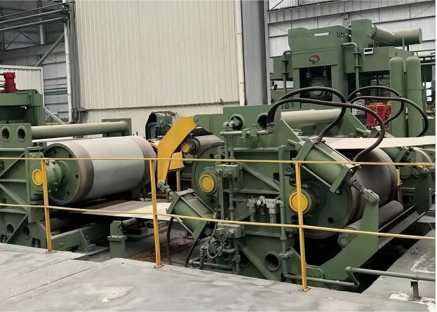
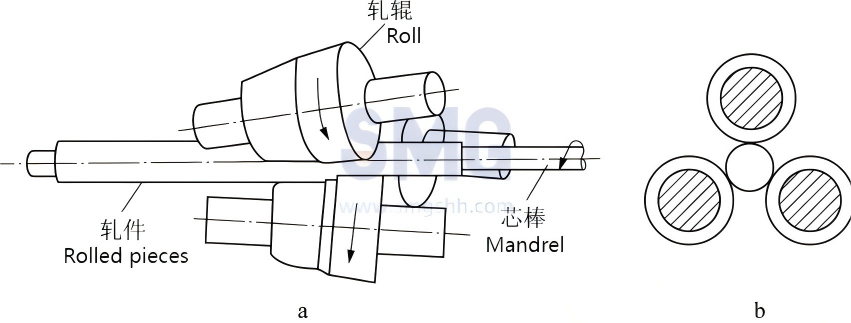
The three-roll skew rolling tube mill (Figure 1) has work rolls mounted on two frames, one of which is fixed while the other can rotate around the mill's central axis, allowing adjustment of the entry angle. The blank tube becomes a rough tube in the deformation zone (Figure 2) through biting, wall reduction, leveling, and roundness restoration. Figure 1 Rolling method of three-roll cross rolling pipe mill Figure 2 Deformation zone of the three-roll cross rolling pipe mill Features During skew rolling and spiral rolling, the metal undergoes continuous periodic action from the rollers and mandrel in the deformation zone, causing changes in both shape and size. The advantages of the Assel tube mill include long mandrel rolling, easy mill adjustment, convenient replacement of roll parts, high surface quality of the steel pipe, and high dimensional accuracy. Its disadvantages are low production efficiency and susceptibility to tail triangle defects when producing thin-walled pipes. This type of tube mill is mainly used for producing bearing tubes and high-precision thick-walled pipes for firearms. Wall thickness tolerance can be controlled within ±3% to ±5%, and outer diameter variation can be ±0.5%. Tail Triangle The deformation of the three-roll skew rolling pipe mill is actually a process from a circle to a triangle and then back to a circle (Figure 3). When rolling thin-walled pipes, the metal has a strong tendency to expand in diameter. The arrangement of the three rollers cannot restrain this tendency; instead, it flattens the thin-walled pipe, which has low bending resistance, and forces it into the roll gap. The resistance from the internal mandrel causes the laterally flowing metal to squeeze even the pipe wall sections that are momentarily undeformed into the roll gap, promoting the expansion of the triangle shape. The front end of the rough pipe and the pipe body do not form a triangular shape due to the influence of the 'rigid tail.' When rolling reaches the tail, the 'rigid tail' has disappeared, resulting in the formation of a tail triangle. The severity increases with higher elongation rates and longer lengths of wall thickness reduction zones. Figure 3 Schematic diagram of the tail triangle cross-section Improved Types When the Assel pilger mill rolls thin-walled pipes, a triangular bell mouth (commonly known as the tail triangle) appears at the end of the steel pipe, causing rolling jams. Therefore, the old type of Assel pilger mill cannot produce thin-walled pipes with an outer diameter to wall thickness ratio greater than 12. To solve this problem, several improved types have been developed. Transvaal Type Pipe Rolling Machine 1967, the French company Vallourec and the British company British Steel Tube jointly developed a new type of three-roll tube mill that can change the roll feed angle during the rolling process. It was developed based on the Assel tube mill and is essentially still an Assel tube mill, but one of the two stands of the mill frame is designed as a rotatable movable stand, that is, the frame consists of a fixed stand A and a rotary stand B. The rotary stand is on the steel pipe entry side, with a rotation angle of 0°–30°, resulting in a feed angle of 3°–10°, which can be continuously varied. Unlike the Assel tube mill, during normal rolling, the maximum allowable feed angle can be used; at the end of the rolling process, the rotary stand can be quickly and accurately rotated to reduce the feed angle, enlarge the orifice, and when rolling the tail end of the blank tube, only slightly reduce the wall thickness without forming a tail triangle. By using small deformation and low speed, the tail triangle effect can be eliminated or reduced. The tube mill can roll thin-walled pipes smoothly without affecting production capacity. The Transvaal type tube mill can roll blank tubes with an outer diameter to wall thickness ratio greater than 20, and even larger. Quick opening method The quick-opening method was developed after the Transval-type tube rolling mill. Near the end of the rolling process, the rollers are quickly raised to leave a short section of unthinned pipe at the tail end, forming a 'rigid rear end' to eliminate the tail triangle. The quick-opening method can be divided into two types: the flat-lift method and the inclined-lift method. The inclined lifting method can be further divided into two types: three-roll quick opening and top-roll single-roll quick opening.For the three-roll quick opening type, a quick-opening hydraulic cylinder needs to be installed under the screw-down (press-down screw) on the roll chock at the exit side of the mill housing. When the steel pipe is rolled to the tail end, the quick-opening cylinder releases pressure rapidly. Driven by the two existing balance cylinders, the roll chock at the exit side lifts up quickly, causing the rolls to rotate at a certain angle around the support center on the entry side and tilt upward. As the pass opens, a "rear rigid end" is formed at the tail end of the steel pipe, allowing the hollow billet to pass through the pipe mill smoothly. For the top-roll single-roll quick opening type, a hydraulic quick-opening device is installed between the top roll adjustment mechanism and the roll chock. Its function is to start operating when rolling is about to end, instantly and rapidly opening the roll throat. This allows the tail end of the steel pipe to pass without being rolled, eliminating the tail triangle defect and enabling the rolling of thin-walled pipes.A connecting ring is used to limit the stroke and meet the operation requirements. When the piston moves inward, the top roll is lifted, realizing pressure-free rolling on the tail of the hollow billet and thereby preventing the formation of a triangular bell mouth at the tail end of the hollow billet. Most newly built Assel pipe mill units adopt the top-roll single-roll quick opening technology. Tail loss prevention device In 1986, the tail-lossless device was designed and developed by the Hofors plant of SKF in Sweden. Installing the tail-lossless device at the entry end of the Avesta rolling mill not only achieved the purpose of eliminating the tail triangle but also did not increase cutting loss. In fact, this device is a type of pre-rolling mill, serving as an auxiliary device on the Avesta rolling mill. When rolling thin-walled pipes, the tail end of the rough pipe undergoes pre-wall-reduction before entering the main rollers of the Avesta mill, reducing the amount of wall reduction during rolling, thereby preventing the formation of a tail triangle without the need to cut off the final rolled section. The Swedes invented the use of four small pre-rolling rollers. When switching steel pipe specifications, it is necessary to adjust the height of the rolling centerline. However, achieving stepless adjustment with these four small pre-rolling rollers is quite difficult. In 1988, the German Miil plant purchased this technology. After improving it to use three small pre-rolling rollers, the pre-rolling device was named the Tail-Lossless Device (Figure 4). The improved device is supported by three pneumatic floating supports to maintain alignment with the rolling centerline. Inside the rolling mill, there are three small rollers, which are not driven. Each small roller can be tilted 3°–4° in the required direction, and their opening and closing is controlled by a hydraulic cylinder lever system. Before rolling reaches the tail end, the three small rollers are in the open position, with a throat diameter greater than the outer diameter of the rough pipe, ready to work. When rolling reaches approximately 250 millimeters from the tail end, the hydraulic cylinders operate, closing the three small rollers to perform wall reduction on the tail of the rough pipe. This produces interconnected helical lines on the outer surface of the steel pipe, helping to ensure a smooth surface and uniform wall thickness at the tail end, preventing the formation of a tail triangle as the steel pipe enters the main Avesta mill rollers for further rolling. After the rolling process is complete, the hydraulic cylinders reverse, and the three small rollers open again, returning to the ready-to-work position. Figure 4 Transmission schematic diagram of the improved tail-less loss device

Blast Furnace - Converter Production Process
2025-10-23

Blast Furnace - Converter Production Process

In the blast furnace-converter production process, sinter ore, pellet ore, and a portion of iron ore are used as raw materials. In the blast furnace, coke serves as both fuel and reducing agent (a portion of coal is often used as a substitute for coke) to reduce and smelt iron ore into liquid pig iron. Then, in the converter, the liquid pig iron and scrap steel are refined into liquid molten steel, which undergoes secondary refining to obtain qualified finished molten steel. The molten steel is continuously cast into steel billets, which are then rolled into finished steel products of various shapes and sizes. Iron and steel integrated enterprises adopting the blast furnace-converter steel production process are generally equipped with a coking plant and corresponding chemical plants. Some enterprises also have additional downstream processes, such as surface treatment, cold rolling, cold drawing, and heat treatment. Before the 1970s, the process composition of the blast furnace-converter production process was: blast furnace → converter → ingot casting → blooming/breaking down → steel rolling to finished products. Later, driven by technological progress and integrated process optimization, the process structure of the blast furnace-converter steel production process gradually evolved into a flow consisting of blast furnace ironmaking → hot metal pretreatment → converter steelmaking → secondary refining → continuous casting and rolling. The advantages of the blast furnace-converter steel production process are: large production scale and strong capacity, output of substantial energy such as gas, accompaniment with a variety of useful by-products, and ability to absorb large amounts of social waste. Its main disadvantages include: long process flow, high consumption of raw materials and energy, large greenhouse gas emissions, high pollutant discharge, high and complex requirements for plant construction conditions, large investment, large land occupation for production processes, and low production flexibility.

Angle Steel Production Line
2025-10-16

Angle Steel Production Line

The angle steel production line is a complete set of equipment for realizing the automated processing of angle steel.  Its core lies in completing the continuous production of processes from raw material feeding to punching, cutting, marking and other procedures through the collaborative operation of multiple special-purpose equipment, thereby significantly improving processing efficiency and processing precision. I. Overall Configuration of the Production Line The configuration of the angle steel production line is designed around the principles of "automation and continuity", and it usually consists of 4 core components, with all links connected seamlessly. 1.Feeding Unit: Responsible for automatically conveying bundled angle steel to the main processing line, eliminating the need for manual handling. It mainly includes a feeding rack and a feeding roller table; some production lines are equipped with a silo to realize unmanned material replenishment. 2.Processing Unit: The core of the production line, which centrally completes key processes such as punching, marking, and cutting. It is composed of equipment like CNC punching and marking machines and CNC cutting machines. 3.Conveying Unit: Connects various processing equipment and transfers angle steel between different processes via roller tables or manipulators, ensuring the production process is uninterrupted. 4.Unloading and Sorting Unit: The finished angle steel (after processing) is automatically conveyed to the unloading rack. Some high-end production lines are equipped with sorting mechanisms to stack the angle steel by specification or order. II. Introduction to Core Equipment The processing accuracy and efficiency of the production line are mainly determined by 3 types of key equipment, each with clear and complementary functions. 1.CNC Angle Steel Punching and Marking Machine Core Functions: Simultaneously complete the punching and marking of angle steel (e.g., specifications, material, production date) without the need for secondary processing.  Key Features: Adopts a CNC system for positioning, with the punching position accuracy reaching ±0.1mm; supports multiple hole types (round holes, slotted holes); the marking content can be flexibly set via software. 2.CNC Angle Steel Cutting Machine Core Function: Based on the set length, it performs high-precision cutting on angle steel that has completed punching, and it serves as the "terminal processing equipment" of the production line. Key Features: Adopts hydraulic or servo drive; the cutting surface is flat and burr-free; the length tolerance can be controlled within ±0.5mm; it supports batch automatic cutting without manual intervention. 3.Feeding Rack and Unloading Rack Feeding Rack: Driven by hydraulic pressure or a motor, it lifts bundled angle steel layer by layer and feeds it into the feeding roller table, adapting to angle steel raw materials of different lengths (6-12m). Unloading Rack: Receives the angle steel that has finished processing; some are equipped with buffer devices to prevent angle steel from being deformed due to collision, and at the same time, it facilitates subsequent manual or mechanical transfer. III. Core Process Flow The process of the angle steel production line follows the logic of "from rough to fine, continuous processing" and consists of 5 main steps, with the overall automation degree exceeding 90%. 1.Raw Material Preparation: Place bundled angle steel (usually plain carbon steel such as Q235) on the feeding rack, and manually complete initial straightening and rust removal (some production lines include a pre-treatment process). 2.Automatic Feeding and Conveying: The feeding rack sends the angle steel into the feeding roller table, and the roller table, driven by a servo motor, accurately conveys the angle steel to the CNC angle steel punching and marking machine. 3.Punching and Marking: According to preset parameters (hole position, hole type, marking content), the CNC system controls the punching die to complete punching; at the same time, the marking mechanism prints marks on the surface of the angle steel, and the two processes are completed simultaneously. 4.Precision Cutting: The angle steel that has completed punching is conveyed to the cutting machine. The cutting machine automatically cuts the angle steel according to the set length, and the cut angle steel directly enters the conveying roller table. 5.Unloading and Inspection: The finished angle steel (after processing) is conveyed to the unloading rack. Manual or automated equipment conducts random inspections on its appearance and dimensions. After passing the inspection, the angle steel is stacked by specification and awaits storage or subsequent assembly.

Wide Slab Continuous Caster: A Key Equipment in Modern Iron and Steel Production
2025-10-9

Wide Slab Continuous Caster: A Key Equipment in Modern Iron and Steel Production

In the integrated "continuous casting and rolling" production chain of modern iron and steel industry, the wide slab continuous caster occupies a core connecting position. It efficiently converts qualified molten steel smelted through the blast furnace-converter process into large-width slabs, providing key raw materials for the subsequent rolling of high-end steel products such as wide and thick steel plates and hot-rolled coils. It is one of the important indicators to measure the high-end plate production capacity of iron and steel enterprises. Its technical level directly determines the quality stability, production efficiency and market competitiveness of steel products. The wide slab continuous caster is an important category of continuous casting equipment, specifically referring to continuous steel casting equipment capable of producing slabs with a width ≥ 1500mm (in the industry, slabs with a width of 1500-2200mm are usually defined as conventional wide slabs, and those with a width of more than 2200mm as ultra-wide slabs). Compared with ordinary slab continuous casters, the core differences lie in the design and control accuracy of key components such as mold width, roll arrangement, cooling system and width adjustment mechanism, which need to meet the requirements of uniform solidification, shape control and quality assurance of large-section slabs. Compared with the traditional ingot casting process and ordinary slab continuous casters, the advantages of wide slab continuous casters are reflected in three core dimensions: High production efficiency: It realizes the continuous production from molten steel to slab, and the production cycle is shortened by more than 60% compared with ingot casting. The annual output of a single wide slab continuous caster can reach 1-2 million tons, which greatly increases the production capacity of the enterprise. Excellent slab quality: Through technologies such as mold electromagnetic stirring, dynamic soft reduction and precise secondary cooling, internal defects of slabs such as porosity, segregation and inclusions are effectively reduced, and the slab qualification rate can reach more than 99%, laying a foundation for the subsequent rolling of high-end steel products. Good cost-effectiveness: Continuous production reduces the heat loss of molten steel, and the energy consumption per ton of steel is reduced by 15-20% compared with ingot casting; at the same time, it eliminates the ingot blooming process in the ingot casting process, and the metal yield is increased by 5-8%, significantly reducing production costs. The technical difficulties of wide slab continuous casting are concentrated on "uniform solidification and quality control of large-width slabs": First, the large transverse temperature gradient of wide slabs is prone to central porosity and segregation, which requires dynamic soft reduction technology to apply pressure at the solidification end of the slab to compact internal voids; Second, the large width of the slab leads to uneven flow of molten steel in the mold, which is prone to surface longitudinal cracks, requiring optimization of submerged entry nozzle structure and electromagnetic stirring parameters; Third, ultra-wide slabs are prone to transverse bending and bulging during cooling and straightening, requiring precise design of roll arrangement and side pressure control system. The output of the wide slab continuous caster is directly connected to the high-end plate market. After subsequent rolling, its slabs are widely used in key fields of the national economy: in the shipbuilding field, it is used to produce wide and thick steel plates for hull structures; in the bridge engineering field, it supplies main beam and web steel plates for long-span bridges; in the petrochemical field, it is used to manufacture steel plates for large pressure vessels; in the construction machinery field, it produces high-strength steel plates for the arms of excavators and cranes; it is also used in the production of high-end products such as automotive sheets and pipeline steel. As a "throat" equipment for high-end plate production in modern iron and steel industry, the technical development history of wide slab continuous caster is a microcosm of the transformation of iron and steel industry from "scale expansion" to "quality improvement". From technology introduction to independent innovation, the breakthrough of China's wide slab continuous casting technology has not only supported the independent supply of the domestic high-end steel market, but also promoted the overall technical upgrading of the iron and steel industry. In the future, with the in-depth integration of intelligent and low-carbon technologies, the wide slab continuous caster will play a more important role in ensuring the supply of key equipment materials for the country and achieving the "double carbon" goal.

Home

Projects

whatsApp

email